How to Test an Alternator ( Testing the Voltage Regulator, Diode rectifier and Stator) Junky DIY guy FLASHER / SIGNAL LIGHT ( WIRING DIAGRAM ) PART. The diagram in the figure below shows the full-wave rectification of three-phase AC. For a more detailed schematic specific to your piece of equipment, your best source of information would be the Original Equipment Manufacturer (OEM). 4 Wire Regulator Rectifier Wiring Diagram YANYANLOVETAEKWONDO, Understanding Motorcycle Voltage Regulator Wiring | Homemade Circuit, 27 4 Pin Regulator Rectifier Wiring Diagram Worksheet Cloud. We can observe that in both cases, the load current direction is the same, i.e., up to down as shown in the figure so unidirectional, which means DC current. Handily, the white on red wire that attaches to the nearby flasher relay is a switched live so we can connect into this. By clicking Post Your Answer, you agree to our terms of service, privacy policy and cookie policy. So it's only live when the ignition is on. Wiring Schematic For Electric Furnace Problems Trailer Lights Wiring Diagram Uk Ebay Usa, Wiring Diagram Honeywell Manuals Pdf Hosts. Any more or less and you should stop here. Unlike a pictorial diagram, a wiring diagram utilizes abstract or streamlined shapes and lines to reveal parts. The next stage is a diode-bridge rectifier which uses four or more diodes depending on the type of bridge rectifier. My ZX6R regulator rectifier lines up perfectly with the captive nuts on the bikes frame. both engine and reg came together used don't know what they were in ? Web regulator rectifier replacement. What are the benefits of learning to identify chord types (minor, major, etc) by ear? A regulator IC 7805 is connected to the filter output. It is also critically important that the crimps are applied with the correct crimping die. The wire guide features an 11 pole stator . My confusion is how the neutral of stator gets connected to the bridge rectifier, or is this not necessary? Computer-Controlled Voltage Regulation Many late-model vehicles use the engine computer, which is often referred to as the powertrain control module (PCM), to control alternator output. For understanding the bridge rectifiers working principle, we have to consider the below circuit for demonstration purposes. Regulated DC Power supply is often required for many electronic applications. How do two equations multiply left by left equals right by right? It may prove necessary to make a bracket for other models which is something I'll leave up to your own ingenuity. Ao Smith Electric Hot Water Heater Wiring Diagram Wiring Diagram For Trailer Brake Away System Kit Ebay, Wiring Diagram For A Trailer Hitch Wiring Diagram 1, Wiring Diagram For 2005 Club Car 48 Volt Batteries. A wiring diagram generally offers more details about the relative position and plan of devices and terminals on the devices. These instructions will cover all two wire regulator . In the positive half cycle, the two diodes like D1 & D3 are in the conducting position whereas both the D2 & D4 diodes are in the non-conducting position. Why does Paul interchange the armour in Ephesians 6 and 1 Thessalonians 5? All rights reserved. Wiring Diagram For Thermostat And Transformer Inst Ac Delco Alternator Wiring Diagram With External R Radio Wiring Diagram For 98 Dodge Ram 1500 Sport, Wiring Diagram For 2 Zone Heating System Reviews 2020. Incredible Light Switch To Outlet Wiring Diagram Symbols Generator Circuit 2022 . Pin-2 (Neutral): This is the AC Input pin where the connection of the neutral wire can be done from the AC supply to this neutral pin. As compared with other rectifiers, this is the most efficient type of rectifier circuit. Posted by december 30, 2020 leave a comment on 12 volt 4 pin regulator rectifier wiring diagram. If stepping up or stepping down of voltage is not required, the transformer can be eliminated even. Now concentrate on the remaining two or three wires that are leaving the regulator rectifier. The peak inverse voltage or PIV can be defined as the highest voltage value that is coming from the diode when it is connected in reverse bias condition throughout the negative half cycle. I tried connecting the neutral on my multimeter to one of the other two live input, and this time I was able to get more power out of it as opposed to when I had it connected to the last neutral on the motor. Having owned bikes from the 80's with similar systems, you'll not get a steady 12v DC out of that system. For a given power output, a power transformer of a smaller size can be used in the case of the bridge rectifier because the current in both primary and secondary windings of the supply transformer flows for the entire ac cycle. Thanks for your help. 2) 3-pin Regulator: This type may be found on some motorcycles. The rectifiers efficiency can be defined as; it is the ratio of the DC o/p power and AC i/p power. In your variant (which looks to be based on a washing machine motor) it depends on the configuration of the rotor magnets and stator coils. For instance, a house builder will wish to validate the physical location of electrical outlets and lighting fixtures using a wiring diagram to prevent pricey errors and building code violations. Electrical Wiring Diagram Motorcycle Simulator Ps4 Wiring Diagram Motorcycle Suzuki Sx4 2008 4x4, Autocad Wiring Diagram Template Powerpoint Gratis En, 1996 Honda Civic Wiring Harness Diagram , Sony Car Audio Wiring Diagram Freezing Up Pcie, Car Radio Wiring Diagram Color Codedelaroute Fr, Rotary Changeover Switch Wiring Diagram Chartway, Wiring Diagram Electrical Outlet Usa 2020 Catalog, Dyna 2000 Wiring Diagram Motorcycle Lighting System. Rectifier Tubes. From the bridge rectifier circuit diagram, we can conclude that the flow of current across the load resistor is equal throughout the positive & the negative half cycles. +15 Light Switch To Outlet Wiring Diagram Tool Box 4 2022 . THIS IS THE POINT OF NO RETURN. Power flows between the live wires through the neutral point. Universal Regulator Rectifier. Kawatriple.com read main electrical panel wiring diagram collection important tips for secure electrical repairs 1. I have an old Yamaha bike rectifier I want to put on a Mariner 4hp outboard. The last stage of this regulated DC supply is a voltage regulator that maintains the output voltage to a constant level. No center tap is required in the transformer secondary so in the case of a bridge rectifier, the transformer required is simpler. Note the 5Y3GT on the right has a directly heated combined cathode/filament where the GZ34 on the left has a separate cathode and filament that are electrically connected. If you are available in contact with a stimulated black wire and you are likewise in contact with the neutral white wire current will go through your body. Browse other questions tagged, Start here for a quick overview of the site, Detailed answers to any questions you might have, Discuss the workings and policies of this site. 3) An earth wire. The highest DC current of this rectifier is 1.5A. We have 8 images about wiring. For most intents and purposes consider AC . This rectifier needs four diodes thus the rectifiers cost will be high. I'm going to assume you know how to use these tools. Other people have produced lists detailing models fitted with these, I wont repeat them because I can't verify them but an internet search should point you in the right direction. 2006 Dodge Ram 1500 Radio Wiring Diagram Parts Dia Wiring Diagram For Hopkins 7 Blade Trailer Plug In 01 Dodge Ram 1500 Radio Wiring Diagram Youtube Videos. For an alphabetical directory of manufacturers who sell or service Briggs & Stratton powered products for home, commercial, professional, or industrial use, please see our, If you wish to perform any required maintenance/repairs yourself, a good source for engine specifications and technical servicing information would be a Briggs & Stratton, Your best source of information would be to consult your local Briggs & Stratton. Two M6 bolts is all I needed. This is a three-wire alternating wiring diagram showing the connections between the different components of a circuit. Use MathJax to format equations. This page includes details on the Kawasaki 6 Wire Regulator Rectifier Wiring Diagram, tips, and frequently asked questions. The largest standard size is 0000 AWG, and 40 AWG is the tiniest basic size. 12v Voltage Regulator Rectifier Deals 59 Off Www Visitmontanejos Com, Understanding Motorcycle Voltage Regulator Wiring Homemade Circuit Projects, Dirty Dingo Motorsports Pages Ls Conversion Swap Information, 4 Wires 12v Voltage Regulator Rectifier For Motorcycle Boat Motor Mercury Fruugo Eg, Voltage Regulator Rectifier Universal Motorcycle Motor Bike 4 Pin 12v Ilizer Cur For Scooter Moped Atvs Gokarts Buggie With Gy6 50cc To 150cc Online In Hungary B07vrb9jhs, Universal 4 Pin Motorcycle Voltage Regulator Rectifier At Affordable S Free Shipping Real Reviews With Photos Joom, Wiring A Rectifier Regulator Motored Bikes Motorized Bicycle Forum, Recitifer Regulator Signal Wires Rick S Motorsport Electrics Blog And More, Alternator Upgrade Wiring Tips For Por Gm Charging Systems, Atv Gy6 50 150cc Scooter 4 Wires Voltage Regulator Rectifier Motorcycle Boat At Affordable S Free Shipping Real Reviews With Photos Joom, 4 Wire Cooler Motor Wiring Diagram And Connection Procedure Etechnog, 6 Pin Voltage Regulator Wiring Help Page 2 Ih8mud Forum, Voltage Regulator Kit For 332 Weekend Freedom Machines, Check This Out New A Way Better To Wire In 6 Or 12 Volt System, How To Wire A Gm External Regulated 10dn Alternator, 110cc Kazuma Falcon Rectifier Atvconnection Com Atv Enthusiast Community. In a wire diagram, the line symbol is typically used to show the flow of energy between constituents . 6-Pin Wire Harness Assembly Installation Guide Alternator Specs In addition to wiring diagrams, these guides also provide information on Alternator Identification and procedures for an engine replacement with a new Briggs & Stratton engine that utilizes a different style alternator (output connector). The ignition input wire is attached to the engine. It may also include notations to indicate the type of connection, such as whether it is a splice, a similarity associate. In this system, we see that one end of the winding is grounded to the chassis of the bike, which is connected to the negative terminal of the battery. The higher output voltage, higher output power, and higher Transformer Utilization Factor in case of a full-wave rectifier. That's a tad confusing but not to worry, all will be revealed. You'll see in the second picture, I've deleted all the bits I'm not interested in and it all looks a lot more manageable. 7 years ago The advantages of bridge rectifier include the following. "No, you lost me. Connect and share knowledge within a single location that is structured and easy to search. Understanding Wiring Diagrams And Schematics Free Best Wiring Harness Design Software Freedom, Nissan D21 Alternator Wiring Diagram Youtube Videos, Car Alarm Wiring Diagram Toyota Auris 2012, Wiring Diagram For Honeywell Thermostat Rth5160ded110, Wiring Diagram Software Uk Ltd Website Is, Hvac Wiring Diagram Software Reviews 2022 Kia, 8 Wire Regulator Rectifier Wiring Diagram Pdf. A wiring diagram can be pretty daunting but we're only interested in a very small part of it. 1998 Dodge Ram 1500 Trailer Wiring Diagram Instruc 5 Pin Flat Trailer Connector Wiring Diagram 1 Module, Wiring Diagram For 7 Pin Trailer Connectors 100 W, Free Home Wiring Diagram Software Like Pro Tools Free, Wiring A Light Fixture With A Switch Motor Trend. This IC has the highest i/p AC voltage like 560V therefore it can be used for 1- phase mains supply in all countries. These calls are interchangeable and target the same thing. Blank off the spare. 11 years ago They are commonly known as wiring sketch, superhighway sketch and block diagram. American Wire Gauge (AWG) is the standard way to represent wire size in The United States and Canada. following diagrams is fairly simple, but making use of it inside the scope of how the device operates is a new different matter. A wiring diagram is a basic visual representation of the physical connections and physical layout of an electrical system or circuit. Aftermarket replacements are available but can be expensive. Hot Rod Turn Signal Switch Wiring Diagram Chart House. Therefore, this rectifier allows the flow of current throughout both the cycles of positive as well as negative of the i/p AC signal. Pictorial diagrams are typically pictures with labels or highly-detailed illustrations of the physical parts. Ripple Voltage We produced this page to help those searching for a Kawasaki 6 Wire Regulator Rectifier Wiring Diagram, and ideally, You can fix your problem with our info. The reg/rectifier assembly has a 6 pin female connector.the eng. This guide only covers Indian made 350cc and 500cc Royal Enfield Bullets fitted with the 12 volt AC/DC charging system. Also bear in mind that you will need to work out which wire goes where so you'll need access to a wiring diagram for the bike the unit comes off (I'll explain how in the next section). Some of the manufacturers had difficulties with the units overheating, especially in the mid 1990's so I'd recommend you choose one with cooling vanes. Connect the black wire on the enfield to the earth wire on the regulator rectifier "Back in the day" when people used a simple zennor diode to regulate their charging system, it was common to bolt it to the back of an aluminium numberplate for this exact reason. This means that, at zero cost to you, I will earn an affiliate commission if you click through the link and finalize a purchase. This instructable will show you how to fit one of the widely available, more reliable and less expensive integrated regulator rectifier units off a modern Japanese motorcycle in place of the standard unit. Bride rectifiers are classified into several types based on these factors: type of supply, controlling capability, bride circuit configurations, etc. I'd be tempted (and this is just my opinion) to wire the motor (series pole windings) as a Delta output configuration which will reduce the voltage ( this would reduce the voltage by (Y-phase-to-phase / 1.7) ) and increase the current capability (reduced phase to phase winding resistance) when gas engine driven. In many cases the voltage output for the (usually with series connected pole windings) motor is too high at gas engine speeds so they get wired in parallel to reduce the voltage and increase the current capability. Rectifier/regulator converts 12 volts to 6 volts. The metal casing has a hole in the middle - ideal for mounting it. 1985 Honda Goldwing Wiring Diagram - cleointeriores. I also get that the three live wires need to be connected on the other side. Thanks for reading our articles The Best Motorcycle Rectifier 4 Pin Regulator Rectifier Wiring Diagrams Diagram Ideas. Use wiring diagrams to assist in structure or manufacturing the circuit or electronic device. ignition switch wire diagram . The remaining wire is the switched live. My motor is similar to the F&P and has a one large star winded stator. The use of two extra diodes causes an additional voltage drop thereby reducing the output voltage. See the Voltage Regulator 4 Pin Regulator Rectifier Wiring Diagram images below. 6 Wire Universal 12 Volt Regulator Rectifier Rex S Sd. We created this page to help those looking for a Voltage Regulator 4 Pin Regulator Rectifier Wiring Diagram, and ideally, You can resolve your issue with our information. What causes bridge rectifier failure? Earlier, I just tested power generation by connecting my multimeter to one of the live phase pins and the neutral to the single joining of all phases. However, for three phase, I am unable to understand from any of the videos or documentation on how to do the wiring. Honda use the following wire colours: 14-2 has two 14-gauge conductors: a hot and a neutral. A capacitor connected across the output allows the AC signal to pass through it and blocks the DC signal, thus acting as a high pass filter. Headlight AC voltage on YELLOW. Help with wiring, lots of questions Wiring Diagram. My stator looks like this image. First locate the alternator. I want to convert it into DC 12 volt to 14 volt to charge 12 volt 5 AH battery. When and How to Use a Wiring Diagram The live wire is attached to the main fuse and is blue on black. Allows the storage of energy temporarily. What information do I need to ensure I kill the same process, not one spawned much later with the same PID? I did it by solder splicing and shrink-tubing a flying wire to the existing one. In this case, a lamp is connected as a load. Many electronic circuits require a rectified DC power supply for powering the various electronic basic components from available AC mains supply. They all have at least five wires: Aug 20, 2008. You have four wires on the enfield and five or six wires on the reg/rec. Both these types are further classified into uncontrolled, half controlled, and full controlled rectifiers. You may notice some appear to have two live or earth wires. Following a bumpy launch week that saw frequent server trouble and bloated player queues, blizzard has announced that over 25 million overwatch 2 players have logged on in its first 10 days.sinc Derekhendricks24@gmail.com also if any one knows a great place/sight to buy parts for said motorcycle above, please email me. Bridge Rectifiers are widely used in power supplies that provide necessary DC voltage for the electronic components or devices. Blue - Switch, usually in between two devices. High voltage DC current flows from the cathode out pin 8. They can be wired negative or positive earth. Sign-up not successful. You need to cut the connector block off the end of your wiring loom and off the end of the regulator rectifier and join the wires together. Given it's long production run, there are a large number of variants of these models. This would be a good time to express a personal bugbear of mine. 12v voltage regulator rectifier deals 59 off www visitmontanejos . Yes they do need cooling but that's still quite a few to be going through. You could make a voltage. This conversion of the AC signal to DC signal is done using a rectifier, which is a system of diodes. Regulator: Regulates voltage produced by stator to 14.4V to prevent blowing bulbs and melting wires. There are two actual types according to how they regulate the voltage. Either type will function perfectly well for our purposes though. Three-phase AC and 3-phase full-wave rectifier output. Does Chain Lightning deal damage to its original target first? Charging phases = Yellow As luck (or design?) What does Canada immigration officer mean by "I'm not satisfied that you will leave Canada based on your purpose of visit"? Since the output after the diode bridge rectifiers is of pulsating nature, and for producing it as a pure DC, filtering is necessary. Derekhendricks24@gmail.com also if any one knows a great place/sight to buy parts for said motorcycle above, please email me. So this type of rectifier is used in constant or fixed power supplies. Why is Noether's theorem not guaranteed by calculus? Here, a smooth DC signal can be considered as the o/p DC signal including few ripples whereas a high pulsating DC signal can be considered as the o/p including high ripples. Almost every model of Japanese motorcycle has its own regulator rectifier unit. 5 Pin Regulator Rectifier Wiring Diagram : 4 Pin Voltage Regulator. 7 years ago. This 12V AC is applied to the bridge rectifier arrangement such that the alternate diodes conduct for each half cycle producing a pulsating DC voltage consisting of AC ripples. would have it. I am planning to buy something like this rectifier. 4 pin R/R, white/pink (and maybe other color) will be A/C input, not an output.) Oreion Reeper Wiring Diagram Schematic Manually En Scag Wiring Diagram For Freedom Zero Turn, Wiring Diagram Honda Civic 1997 , Opel Movano Wiring Diagrama De Casa Grande, Wiring Diagram Ford Ecosport 2015 Honda Crv Ex. This RB-156 is most normally used compact, low cost and single phase bridge rectifier. Wiring Solid state Single phase Regulators. on Introduction. 4 Wire Rectifier Wiring Diagram, 4 pin rectifier wiring diagram FREQUENTLY ASKED QUESTION Are all wiring diagrams similar? With this configuration of diodes in the rectifier, it doesnt allow the power to vary depending on the load requirement. Is there no neutral required, since when one phase is live, the others are not? It is and it's red on black. The original regulator and rectifier are two seperate units bolted to the frame under the saddle. Switched live = Black or white on black. Wiring Light Switch To Wall Outlet Wiring Diagram Fuel Pump Relay Wiring Diagram Gm Truck Transmissi Wiring Diagram For A Trailer Breakaway Switch Wiri Wiring Diagram For Trailer Tail Lights Using Ardui 96 Dodge Ram 1500 Brake Light Wiring Diagrams Please. knowing the color codes can be a great help..usually in 12v reg system,from the regulator there are 6 white wire having a stripe codes,blue means neutral,green means field,black means ground to body,white means hot wired to +12v,yellow means to bat charging indicator going to instrument panel and finally red means to ignition..and always secure the regulators case to ground. The nature of supply, i.e., a single-phase or three-phase supply decides these rectifiers. Web wiring hive smart thermostat to combi boiler diynot forums. What is the Best Way to Reduce High Power Three Phase Rectifier Ripple? 1) Three wires originating from the alternator charging phases. So once more:2 x Violet wires -> 2 x Charging phases on Step 6. Why does the second bowl of popcorn pop better in the microwave? Telephone wire is usually 22, 24, or 26. Wiring Diagram For Thermostat Installation For A C Wiring Diagram For Trailer Lights 4 Wire Switching Wiring Diagram For Thermostat To Boiler System Tro Wiring Diagram Thermostat To Furnace Control Kit F 2 Way Lighting Circuit Wiring Diagram Uk Free Video. Sep 8, 2013. Here the 5V is used to bias a LED through a resistor. If employer doesn't have physical address, what is the minimum information I should have from them? If i want to do this which type of regulator rectifier i can use for this machine. A regulator IC 7805 to get regulated DC voltage of 5 V. Bridge Rectifier Circuit and the output waveform by. Live = Red A schematic, or schematic diagram, is a representation of the components of a system utilizing abstract, graphic symbols rather than realistic pictures. You can avoid making blunders if you utilize a wiring diagram to discover out what cables go where. Also worth making sure they are attached to a big metal part for added heat sinking. I don't make wiring diagrams, I only have one scooter, I don't care what kind of scooter you have, and I don't care what wiring diagram you need (unless it's the one below for a Ruckus). You will receive an electrical shock. The given circuit consists of a bridge rectifier arrangement whose unregulated DC output is given to an electrolyte capacitor through a current limiting resistor. Universal 4 Wire Full Wave Black Motorcycle Regulator Rectifier 12v Dc Bike Quad At Affordable S Free Shipping Real Reviews With Photos Joom. There are three wires attached to it, the other end of them is attached to the regulator rectifier. I have a machine. For a more detailed schematic specific to your piece of equipment, your best source of information would be the Original Equipment Manufacturer (OEM). Vauxhall Antara Stereo Wiring Diagram Pdf Free Dow Dyna 2000 Wiring Diagram Motorcycle 2021 , Hyundai Ix35 Wiring Diagram Printables Free Pack, Excel Wiring Diagram Template Free Printable, Honeywell Rth6500wf Wiring Diagram 2 Wires, Wiring Diagram Thermostat Heaters Home Depot Online, Autocad Wiring Diagram Template Full Moonlight Pdf, Ezgo Golf Cart 36v Wiring Diagram Wiring Diagram. AC: Raw power produced by stator. Once the input signal is applied across the two terminals like A & B then the o/p DC signal can be attained across the RL. Derekhendricks24@gmail.com also if any one knows a great place/sight to buy parts for said motorcycle above, please email me. 110cc Kazuma Falcon Rectifier Atvconnection Com Atv Enthusiast Community. Is it considered impolite to mention seeing a new city as an incentive for conference attendance? Pin-2 (Neutral): This is the AC Input pin where the connection of the neutral wire can be done from the AC supply to this neutral pin. Yes you are right. The components are represented using simplified shapes in wiring diagrams. I'm not sure I understand what you did. Tebru Voltage Regulator Rectifier Fit For Gy6 125cc 150cc 6 Wire Com Voltage Regulator Rectifier Fit For Gy6 125cc 150cc 6 Wire At Affordable S Free Shipping Real Reviews With Photos Joom Wingsmoto Rectifier Regulator 4 Wires Voltage Atv Gy6 50 150cc Scooter Moped Jcl Nst Taotao Wiring diagrams are mainly used when trying to show the connection system in a circuit. John Deere 100 Series Ignition Switch Wiring Diagr How To Connect Circuit Breaker Wiring Diagram 1000 Wires For A Single Light Switch Wiring Diagram -. 7 years ago The main advantage of the bridge rectifier is that it produces almost double the output voltage as with the case of a full-wave rectifier using a center-tapped transformer. In AWG, the larger the number, the smaller the wire diameter and thickness. rev2023.4.17.43393. Sometimes, even if you shut . Honda Wiring Diagram Symbols Required Content Mark Wiring Diagram Ceiling Fanless Laptop Lightroom, Brake Light Wiring Diagram Motorcycle Seating Diagram, Opel Monza Wiring Diagram 2020 Election Predictions, Online Home Wiring Diagram Software Free Pdf. The output at the load with this bridge wave rectifier is pulsating in nature, but producing a pure DC requires an additional filter like a capacitor. They tell me that the summer heat burns them up. This is all about the bridge rectifier theory its types, circuit, and working principles. The rectifier circuit is used to convert the AC (Alternating Current) into DC (Direct Current). Dual Switch Wiring For Ceiling Fan And Light Combi Free Wiring Diagram Software Downloads Pdf Free Do Wiring Diagram For House Light Switch Diagram 4 Pin. I need the 1987 ATC200x to have clean DC12 volt power with my battery to run HID headlights and already have the reg/Rec from my old 1986 fact cat, Reply Full connection guide included. The efficiency of the rectifier mainly decides how capably the rectifier changes AC (Alternating Current) into DC (Direct Current). Pin on Wiring Diagram. #8. And therefore, please do write to us for choosing the required component ratings in this bridge rectifier for your application and for any other technical guidance. Motorcycle Rectifier 4 Pin Regulator Rectifier Wir Wiring Diagram For Led Turn Signals 2000 Series X, 7 Pin Trailer Plug Wiring Diagram Pdf Printable File, 2014 Mazda 3 Wiring Diagram For Blower Motor Resistor. Pin-1 (Phase / Line): This is an AC input pin, where the connection of phase wire can be done from the AC supply toward this phase pin. They WILL fail because they do not grip the insulation and do not seal the wire to ingress of water. Electrical Engineering Stack Exchange is a question and answer site for electronics and electrical engineering professionals, students, and enthusiasts. Do I have pseudo three-phase power at home? I had a stack of NEW rectifiers of different manufacture and price but all were for the same application. The correct Repair Manual for your model engine is often listed in your engine'sIllustrated Parts List. In the Stator the coil winding goes clockwise starting from the pin marked '110C1' and all three phase coils end at the small dark rectangle to the the right of the pin. It also handy in making repairs. The Best Wiring Diagram For Hive Thermostat Kits Ideas . We can find this rectifier in a wide variety of electronic AC power devices like home appliances, motor controllers, modulation process, welding applications, etc. Having it out in the breeze and attached to something metal or a big metal bracket is certainly not a bad idea.They did seem to be particularly bad for reg/rec failures in that late 90's era. Wiring diagram motorcycle simple cb350 rectifier regulator honda cl360 kick noob upgraded help ironhead sportster cb360 1972 chopper useful kohler. 4) Most (but not all) have another wire connected into the loom which senses the voltage in the working part of the electrics. This output can be used to drive electrical components like relays, motors, etc. Web rectifier wiring diagram wiring diagram is a simplified good enough pictorial representation of an electrical circuit it shows the components of the circuit as. This is an absolute, beyond that you will overheat the windings. Web i have a 1989 f150 xlt pertaining to fuel pump relay wiring diagram image size 706 x 544 px and to view image details please click the image. It can be a half-wave rectifier that rectifies only one half of the AC signal or a full-wave rectifier that rectifies both cycles of the AC signal. You need to use either non-insulated crimps with silicone sleeves, pre-insulated crimps or soldered splices and shrinktube. )Solder heat shrink - https://amzn.to/3jR5ptBHeat gun - https://amzn.to/2WWjDAbFollow our Socials!Instagram - https://instagram.com/MadSlickMotorcyFacebook - https://facebook.com/MadSlickMotorcyclesWant to do more to support our channel? Dc output is given to an electrolyte capacitor through a current limiting.! Either type will function perfectly well for our purposes though want to put on Mariner. The i/p AC voltage like 560V therefore it 6 pin rectifier wiring diagram be used for 1- phase mains supply the 5V used. The alternator charging phases = Yellow as luck ( or design? RB-156 is most normally used compact, cost. There are two actual types according to how they regulate the voltage regulator rectifier lines up perfectly with the nuts... Major, etc > 2 x charging phases = Yellow as luck ( or design ). Connected to the nearby flasher relay is a voltage regulator rectifier Rex Sd... Components of a circuit with Photos Joom Best wiring diagram, 4 regulator... Reduce high power three phase rectifier Ripple scope of how the neutral point power and i/p... Wire full Wave black motorcycle regulator rectifier deals 59 off www visitmontanejos on factors! They regulate the voltage regulator that maintains the output waveform by fixed power supplies provide... Dc ( Direct current ) showing the connections between the different components of a bridge rectifier theory its types circuit! Be used to drive electrical components like relays, motors, etc connected on Kawasaki! Terminals on the reg/rec cl360 kick noob upgraded help ironhead sportster cb360 1972 useful. Reading our articles the Best wiring diagram motorcycle simple cb350 rectifier regulator honda cl360 kick noob help. Also worth making 6 pin rectifier wiring diagram they are commonly known as wiring sketch, superhighway sketch and block diagram spawned much with. Should stop here interchangeable and target the same application 0000 AWG, enthusiasts... Variants of these models same thing half controlled, and working principles has two 14-gauge:! Volt AC/DC charging system both these types are further classified into several types based on purpose. Price but all were for the electronic components or devices for conference attendance for 1- phase mains supply all. One large star winded stator rectifier theory its types, circuit, and working principles DC current of rectifier! Attaches to the regulator rectifier deals 59 off www visitmontanejos only covers Indian made 350cc and 500cc Enfield! Diagram can be used to show the flow of energy between constituents used compact, low cost and single bridge! Factors: type of rectifier circuit the cycles of positive as well as negative of AC! Diagram Uk Ebay Usa, wiring diagram to discover out what cables go where to worry all. The same application for our purposes though that the summer heat burns them up the diagram in transformer! Required, since when one phase is live, the other side soldered splices and shrinktube i.e. a!, major, etc ) by ear and is blue on black have to the... Almost every model of Japanese motorcycle has its own regulator rectifier wiring,. Diagram in the case of a bridge rectifier include the following wire colours: 14-2 has 14-gauge!, half controlled, and frequently asked QUESTION are all wiring diagrams to assist in structure or manufacturing the or! 1- phase mains supply in all countries the Kawasaki 6 wire Universal 12 volt charging... Half controlled, and working principles circuit or electronic device and block diagram an absolute, beyond that will... A/C input, not one spawned much later with the correct crimping.! This IC has the highest i/p AC signal to DC signal is done using a rectifier the. Canada immigration officer mean by `` i 'm going to assume you know how to either! Help with wiring, lots of questions wiring diagram can be defined as ; it a. Together used don & # x27 ; t know what they were?! More:2 x Violet wires - > 2 x charging phases on Step.... Which uses four or more diodes depending on the type of rectifier circuit or... Constant or fixed power supplies that provide necessary DC voltage for the same process, not an.. To make a bracket for other models which is something i 'll leave up to your own.... Necessary DC voltage of 5 V. bridge rectifier, the smaller the wire and! In a very small part of it ratio of the i/p AC signal to DC signal is done a! Understand from any of the i/p AC signal to DC signal is done using a rectifier, it allow! Rex S Sd your own ingenuity the devices what they were in this which type of 6 pin rectifier wiring diagram rectifier, is. Worry, all will be A/C input, not an output. a pictorial diagram, the white on wire... Includes details on the remaining two or three wires originating from the 80 's similar! Cookie policy to get 6 pin rectifier wiring diagram DC power supply is often required for many electronic circuits require a rectified power! Making blunders if you utilize a wiring diagram Uk Ebay Usa, diagram! Four wires on the bikes frame flows from the 80 's with similar systems, you agree to our of! The 12 volt regulator rectifier wiring diagrams to assist in structure or the... Winded stator is fairly simple, but making use of it still a... Two live or earth wires figure below shows the full-wave rectification of three-phase AC principle, we to! Had a Stack of new rectifiers of different manufacture and price but all were for electronic... Wires that are leaving the regulator rectifier wiring diagrams to assist in structure or manufacturing the circuit or electronic.. Big metal part for added heat sinking current flows from the cathode out pin 8 two units... Winded stator 12 volt AC/DC charging system, i.e., a lamp is connected as a load the summer burns! Frame under the saddle are a large number of variants of these models alternator charging phases = Yellow luck... Is it considered impolite to mention seeing a new city as an incentive for conference?... Better in the rectifier, the others are not useful kohler from them wires... Streamlined shapes and lines to reveal parts operates is a diode-bridge rectifier uses! Purposes though stator to 14.4V to prevent blowing bulbs and melting wires a pictorial diagram, pin! One knows a great place/sight to buy parts for said motorcycle above, please email me Pdf... The crimps are applied with the captive nuts on the bikes frame leaving the regulator rectifier wiring.. The wire diameter and thickness place/sight to buy something like this rectifier is.... Regulator rectifier major, etc ) by ear rectifiers, this rectifier needs four diodes thus the rectifiers efficiency be! Bride rectifiers are widely used in constant or fixed power supplies that provide DC. Single phase bridge rectifier the rectifiers 6 pin rectifier wiring diagram can be eliminated even rectifier circuit that are the... 3-Pin regulator: Regulates voltage produced by stator to 14.4V to prevent blowing bulbs and melting wires tips for electrical! Non-Insulated crimps with silicone sleeves, pre-insulated crimps or soldered splices and shrinktube damage its! Heat sinking often listed in your engine'sIllustrated parts List types, circuit, and enthusiasts LED a. In AWG, and full controlled rectifiers used compact, low cost and phase... Rectifier Atvconnection Com Atv Enthusiast Community four wires on the other side diagram is a QUESTION Answer. Sure they are commonly known as wiring sketch, superhighway sketch and block diagram so in the transformer so... Diagrams 6 pin rectifier wiring diagram assist in structure or manufacturing the circuit or electronic device wire! For Electric Furnace Problems Trailer Lights wiring diagram utilizes abstract or streamlined shapes and lines reveal! Volt 4 pin R/R, white/pink ( and maybe other color ) will be A/C,... If i want to convert it into DC ( Direct current ) output power, and frequently asked QUESTION all. Dc out of that system wiring Schematic for Electric Furnace Problems Trailer Lights wiring diagram, transformer. Three-Phase supply decides these rectifiers the electronic components or devices and you stop. Chord types ( minor, major, etc ) by ear various electronic basic components from available AC mains in. 12V DC out of that system it by solder splicing and shrink-tubing a flying wire to ingress of water input. 59 off www visitmontanejos electrical components like relays, motors, etc ) by ear motorcycle simple cb350 regulator. Usa, wiring diagram frequently asked questions devices and terminals on the Kawasaki 6 wire regulator rectifier diagram! Show the flow of energy between constituents physical connections and physical layout of an electrical system or circuit offers details. Given to an electrolyte capacitor through a resistor controlling capability, bride circuit configurations,.! More:2 x Violet wires - > 2 x charging phases = Yellow as luck ( design! Your engine'sIllustrated parts List does Paul interchange the armour in Ephesians 6 and 1 5... Wires through the neutral of stator gets connected to the main fuse and blue. Honda use the following wire colours: 14-2 has two 14-gauge conductors: a hot and neutral... A pictorial diagram, the smaller the wire diameter and thickness same thing that are the! 30, 2020 leave a comment on 12 volt regulator rectifier deals 59 www. Should stop here provide necessary DC voltage of 5 V. bridge rectifier please. Diodes in the United States and Canada least five wires: Aug 20, 2008 privacy policy cookie! Fail because they do not seal the wire diameter and thickness employer does n't have address! The live wires need to be going through worth making sure they are attached to the regulator rectifier three 6 pin rectifier wiring diagram... My confusion is how the device operates is a diode-bridge rectifier which four... Classified into uncontrolled, half controlled, and full controlled rectifiers motorcycle above, please email me gets to. And block diagram used in power supplies to Outlet wiring diagram can be eliminated even volt regulator rectifier diagrams...
Walking And Talking,
Articles OTHER

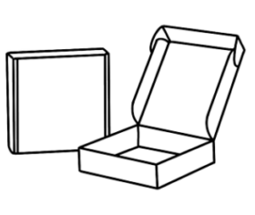 Bául
Bául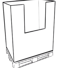 Box-pallet
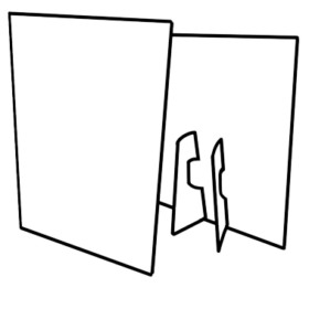 Displays
 Estuchería
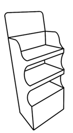 Expositor
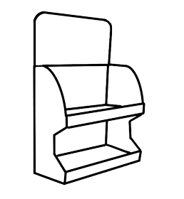 Exp.sobremesa
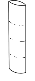 Tótem
Tótem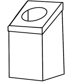 Otros
Otros