More the capacitance will have a larger glitch height. of setup slack will be in this manner:- setup slack = min path (c.p + (capture path + 0.2) + cppr - setup) - max path ( (. Purpose - This paper proposes to study the effect of line resistance and driver width on crosstalk noise for a CMOS gate driven inductively and capacitively coupled VLSI interconnects. VOL is the range of output voltage that is considered as a logic 0. One of the most signicant signal integrity effects is the crosstalk effect. . Lets 0.2ns is common clock buffer delay for launch path and capture path. Hold timing may be violated due to crosstalk delay. The second solution to reduce crosstalk noise, is to increase the Capacitance of Victim load (CV).i.e. Crosstalk plays an important role in deciding the performance reliability of the circuit. Furthermore, as coupling capacitance between wires increases due to the geometry scaling, the design verification process must accurately take into account crosstalk induced effects. Atom The most effective way to fix crosstalk is to use a well-designed layout. Timing Window Analysis Crosstalk timing window analysis is based on the Read more, In the previous article, we have discussed signal integrity, crosstalk, crosstalk mechanisms and the parasitic capacitances associated with interconnects. In deep submicron technologies, crosstalk plays an important role in the signal integrity of the design. The two types of crosstalk effects can be summarized as: Crosstalk glitch: A crosstalk glitch introduces noises into the steady victim . In the previous article, we have discussed signal integrity, crosstalk, crosstalk mechanisms and the parasitic capacitances associated with interconnects. Lets take a example when all aggressor do not switch concurrently. What is Built In Self Test (BIST)? During this event, there is a leakage current which starts flowing from node V to node A through the mutual capacitance Cm due to the leaky nature of mutual capacitance. In this article, we will discuss the effects of crosstalk. Let us consider a situation when wire A switches while neighbor wire B is supposed to remain stable or constant. from the timing windows of the aggressor nets. If the receiving gates RC delay is not in sync with the incoming pulse, it may not even recognize the incoming pulse (1V, 1ps). The above model can be further simplified as shown in figure below. If the height of the glitch is within the noise margin low (NML), Such a glitch is considered a safe glitch. Load determines size of propagated glitch. But, that is not the only thing. <130nm) and below, the lateral capacitance between nets/wires on silicon, becomes much more dominant than the interlayer capacitance.Hence, there is a capacitive coupling between the nets, that can lead to logic failures and degradation of timing in VLSI circuits. Figure-2 shows a typical arrangement of aggressor and victim net. Let's consider aggressor net switches from low to high logic and victim net switches from high to low (opposite). As a result, all conceivable timing violation values owing to crosstalk must be determined early in the design process. Crosstalk is typically generated by unwanted capacitive, inductive, or conductive coupling between circuits or channels. Hence, the third solution to reduce crosstalk noise, is to maintain sharp transitions on aggressor. grounded capacitance is small then the magnitude of glitch will be large. This will affect the smooth transition of the victim node from low to high and will have a bump after half of the transition and this will result in a decrease in the transition time of the victim net. Figure-5 shows safe and unsafe glitches based on glitch heights. Again in case of glitch height is within the range of noise margin low. Crosstalk. Increasing the number of metal layers. Some of the charge is also transferred to the victim. 3. Removing common clock buffer delay between launch path and capture path is CPPR. Crosstalk is the unwanted coupling of signals between adjacent wires or devices in a VLSI layout. The number of repeater is varied for four different cases of stimulations to both lines viz. The DC noise margin only check the glitch magnitude, and the AC noise margin check other attributes. Crosstalk is a phenomenon, by which a logic transmitted in vlsi circuit or a net/wire creates undesired effect on the neighboring circuit or nets/wires, due to capacitive coupling. variation of the signal delay and cross-talk noise. 1.CDEBP Neural Network and Researched on Its Application in Pre-assessments of the Automotive Wiring Harness CrosstalkBP 2.Far-end loop noise- using the estimated crosstalker profile, an estimate of the loop noise present at the far end can be made. . Crosstalk has two major effects: In order to explain the crosstalk glitch, we will consider the following two cases. The answer is it depends on the height of the glitch and the logical connection of the victim net. (comman path pessimism removal). Consider input of driver D switching from logic 0 to logic 1,thus the logic at node V switches from 1 to 0. Clock reconvergence pessimism (CRP) is a difference in delay along the common part of the launching and capturing clock paths. 1. Signal integrity issues due to ground bounce. Signal Integrity addresses two concerns in digital design. In this article, we will discuss the timing window analysis of crosstalk and the prevention techniques of crosstalk. . is captured by the capture flip-flop early. dominant metal aspect ratio it means that in lower technology wire are thin and Again in case of a glitch height is within the range of noise margin low. If the input of any combinational circuit changes due to that we get the unwanted transition at the output which is known as a glitch. So it is important to do a crosstalk delay analysis and fix the timing considering the effect of crosstalk. For example, 28nm has 7 or 8 metal layers and in 7nm its The purpose of this paper is to provide a comprehensive . For setup timing, data should reach the capture flop before the required time of capture flop. Design guidelines for shielding in the presence of power/ground (P/G) noise are presented in this paper. similar cases are for many combinational logic where there would be no effects of crosstalk. 'https://www.googletagmanager.com/gtm.js?id='+i+dl;f.parentNode.insertBefore(j,f);
With each contraction in technology nodes, many things, such as the width of metal wires and transistor size, tend to be downscaled. Refer diagram below to understand the basic model of crosstalk. Technology nodes are easily vulnerable to inductive and capacitive couplings from adjoining interconnects. Kaushik; R. Singh 2009-07-31 00:00:00 Purpose - Process variation has become a major concern in the design of many nanometer circuits, including interconnect pipelines. nodes, many things, such as the width of metal wires and transistor size, tend to be downscaled. In Digital form, it is either in state 1 (high) or in state 0 ( Low) as shown in the figure-1 below. Increase the spacing between aggressor and victim net: Figure-2: Effect of net spacing on crosstalk. In this article, we will discuss the timing window analysis of crosstalk and the prevention techniques of crosstalk. to the adjacent net. What is Design For Testability And Why Is It Important. It implies the delay happening in the output transition of victim due to transition of aggressor. Q2. 1ps) as opposed to another scenario, where the pulse height is low (e.g. The figure below shows how peak voltage is a function of coupling capacitance CC, Victime drive strength RV and rise time on aggressor line. In the situation when the wire and its neighbor wire are switching simultaneously, the direction in which both are switching will affect the amount of capacitance that must be delivered to the destination and also the delay of the switching. Such cases must be considered and fix the timing. Very Good Articles! - This paper proposes to study the effect of line resistance and driver width on crosstalk noise for a CMOS gate driven inductively and capacitively coupled VLSI interconnects., - The paper considers a distributed RLC interconnect topology. Some of the signal integrity effects might occur in your design. Let's consider aggressor net switches from low to high logic and victim net also switches from low to high (same direction). The book begins with a focus on currently available crosstalk delay models, test generation algorithms for delay faults and . The higher Vp is, there are more chances that it would exceed noise margin. Definition of Crosstalk Crosstalk is the interference between signals that are propagating on various lines in the system. So if there is an increase of delay in the data path or launch clock path it may cause a setup violation. <130nm) and below, the lateral capacitance between nets/wires on silicon, becomes much more dominant than the inter layer capacitance. Figure-11, shows the data path, launch clock path and capture clock path. Crosstalk glitch height depends basically on three factors: Closer the nets will have greater coupling capacitance. This will affect the smooth transition of the victim node from low to high and will have a bump after half of the transition and this will result in a decrease in the transition time of the victim net. Inductive crosstalk occurs due to mutual inductance between two nets. VIL is the range of input voltage that is considered a logic 0 or. There are many reasons why the noise plays an important role in the, Higher routing density due to finer geometry, Faster wave formsdue to higher frequencies. M1 is patterned and the unwanted metal areas are etched away and again empty regions are filled with SiO, So there is the formation of parasitic capacitance between two neighbouring M1 nets (same metal layers) which is called lateral capacitance (CL). Hands on experience on the Synopsys ICC2 tool for PD flow stages like in floorplan, powerplan, placement, CTS, routing and signoff in 40nm. Victim is a net which is impacted by aggressor net. physical proximity. VLSI Courses for Students & Freshers (UG/PG), Streamlining Electronics Testing with Automatic Test Equipment, MBIST in VLSI: Ensuring Better Quality Chips, A Quick Introduction To Lockup Latches In VLSI Designs. It stands for Tool Command Language Tcl is interpreter based To interpreter a Tcl script you will require a Tcl Shell - 1.If a net has no driver, it gets the value. In the above figure, tr is the rise time at the aggressor node A, which is related to the gate delay RA as shown in below equation: Essentially, the above figure represents a voltage source connected at aggressor node A with a series capacitance CC. A Faraday cage is a type of shielding used to reduce coupled interferences. The static timing analysis with crosstalk analysis verifies the design with the worst case. The switching If you are a fresher and want to start your career in VLSI and dont know from where you hav Why noise and signal integrity? Crosstalk & Useful Skew; Clock Buffer, Normal Buffer & Minumum Pulse Width Violation; Clock Tree Routing Algorithm; STA,DTA,Timing Arc, Unateness; Transmission Gate,D Latch, D Flip Flop ,Setup & Hold Time; Global Setup &Hold Time; GATE 2020 ECE Digital circuits questions; GATE 2019 ECE Digital circuits questions; GATE 2018 ECE Digital circuits . Figure-12, explains the situations where the hold time could violate due to crosstalk delay. Many other situations may occur which may cause chip failure due to the unsafe glitch. This article explained the signal integrity, crosstalk, crosstalk mechanisms and parasitic capacitances related to interconnects. depends on the switching direction of aggressor and victim net because of this plz correct it. victim net: greater the coupling capacitance, larger the magnitude of This is known as the backward or nearend crosstalk !Once again Thank you for sharing your Knowledge!! Figure-4 shows the CMOS inverter transfer characteristics and Noise margins. ( M2 layer is fabricated above M1 followed by SiO2layer. Out of two mechanisms explained here, Electrostatic Crosstalk mechanism is more significant and problematic than Inductive crosstalk. Let's suppose the latency of path P1 is L1 and for the path P2 is L2. Crosstalk Noise: During the transition on aggressor net causes a noise bump or glitch on victim net. The negative crosstalk impacts the driving cell as well as the net interconnect - the delay for both gets decreased because charge required for the coupling capacitance is less. The high drive strength of the aggressor net will impact more the victim net. A steady signal net can have a positive glitchor negative glitch due to chargetransferred by the switching aggressors through the coupling capacitance. How to prepare for a VLSI profile from scratch? Energy that is coupled from the actual signal line, the aggressor, onto a quiet passive victim line so that the transferred energy "travels back" to the start of the victim line. It could make unbalance a balanced clock tree, could violate the setup and hold timing. If many lines or wire are switching ups ans down, for a long line there will be no much contribution to the crosstalk delay or crosstalk noise. Thank you can you tell me the exact mistakes so that I will correct that .. thanks for your articles. These capacitances are directly proportional to the common area between them and inversely proportional to the gap between them. These capacitances are directly proportional to the common area between them and inversely proportional to the gap between them. This method requires that shield wires are placed on, either side of the critical signals. higher layers (because higher layers have width is more), Use multiple The shields are connected to. The author covers different types of noise, such as crosstalk noise caused by signal switching of adjacent wires, power supply noise or IR voltage . Unfortunately . Crosstalk causes interference in signal because of which signal integrity of the signal gets hampered. Setup violation may also happen if there is a decrease in delay on the capture clock path. A Tcl procedure is defined with the proc command. Interlayer capacitance can be formed not only conjugative metals but also the metals far away to each other, like M2-M4 or M2-M5. Based on whether the multiple aggressors can switch concurrently, the. The VLSI Handbook - Mar 11 2020 For the new millenium, Wai-Kai Chen introduced a monumental reference for the design, analysis, and , RTL and static analysis courses, and much more. drive strength of victim net and decrease the drive strength of aggressor net, Jumping to Vertically This unwanted element is called Signal Integrity. and the capture clock path has negative crosstalk. Required time low. A. Hetzel, and J. Koehl, "Analysis, reduction and avoidance of crosstalk on VLSI chips," in Proceedings of the . In electronics, crosstalk is any phenomenon by which a signal transmitted on one circuit or channel of a transmission system creates an undesired effect in another circuit or channel. 1 coupled network extraction; Their variations have a definite impact to the total line 2 victim aggressor selection; 3 cluster network generation; and capacitance and interline coupling capacitance and result in 4 cross-talk noise computation. either transition is slower or faster of the victim net. If this crosstalk is on a clock signal, it will be even more vital to correct timing breaches promptly as modification of routing for the clock might lead to further timing violations later. This article is being too long, so we will stop here and will continue the remaining part, Signal Integrity and Crosstalk effect in VLSI, Crosstalk Timing Window Analysis and Prevention Techniques, Physical Design Interview Question for experience level 3 Years, Question Set -10, 50 most useful dbGet commands for Innovus, VLSI EDA Companies in India | Top EDA Companies, VLSI Product Companies in India | Top 30 Semiconductor Product Companies, VLSI Service Companies in India | Top 40 VLSI Service companies, Figure-3: Raising and Falling glitch in crosstalk, Figure-4: CMOS transfer characteristics and Noise margin, Figure-5: Safe and unsafe glitch based on glitch heights, Figure-6: Crosstalk delay due to opposite direction switching, Figure-8: Crosstalk delay due to same direction switching, Figure-10: Effect of crosstalk delay on clock tree, Figure-11: Effect of crosstalk delay on setup timing, Figure-12: Effect of crosstalk delay on hold timing. Give me some time I will share everything related to Physical design incuding answers also. Crosstalk has two major effects: Crosstalk glitch or crosstalk noise Crosstalk delta delay or crosstalk delay Crosstalk glitch In order to explain the crosstalk glitch, we Read more, According to a research conducted by Collett International Research Inc., one in five chips fails because of the signal integrity. In this article, we will discuss a very important issue of VLSI design called signal integrity and crosstalk which are responsible for the failure of many ASICs now a day. In VLSI, we have same situation with the nets routed that even nets are at their track but impacted by the noise from other nets. This leakage current will drop the potential of node V, which creates a falling spike or falling glitch on the victim net as shown in figure-2. So signal Integrity could be defined as replication of the entire signal while transmitting from one point to another without any distortion in its quality. A realistic model including the effects of crosstalk and vias is adopted which is not considered in 10. Out of two mechanisms explained here, Electrostatic Crosstalk mechanism is more significant and problematic than Inductive. INTRODUCTION Rapid advances in VLSI technology has enabled us to reduce the minimum feature sizes to sub-quarter microns and the switching times to tens of picoseconds or even less. Case-2: Aggressor net is switching high to low and victim net is at a constant high. In the next article, we will discuss crosstalk glitch and crosstalk delay. crosstalk delay so that the data is launched early. Here is the image for more context: (Source: Team VLSI - Crosstalk Noise and Stack Exchange Network Stack Exchange network consists of 181 Q&A communities including Stack Overflow , the largest, most trusted online community for developers to learn, share their knowledge, and build their careers. also more. The sole distinction between crosstalk delay and crosstalk noise is that the nets are not at steady state values and some switching activities are occurring on both the victim and aggressor nets. Are directly proportional to the common part of the victim net also switches from to! Thanks for your articles noise bump or glitch on victim net is high. 1Ps ) as opposed to another scenario, where the pulse height is within the range of margin. < 130nm ) and below, the performance reliability of the most effective way to fix crosstalk the! Launched early varied for four different cases of stimulations to both lines.! Capture path signals between adjacent wires or devices in a VLSI profile from?! Transition is slower or faster of the launching and capturing clock paths DC noise margin check!: effect of net spacing on crosstalk of metal wires and transistor size, to. Unwanted capacitive, inductive, or conductive coupling between circuits or channels effective way to fix crosstalk is to the. Inter layer capacitance two major effects: in order to explain the crosstalk introduces. Begins with a focus on currently available crosstalk delay only check the glitch is within the margin! Paper is to increase the spacing between aggressor and victim net so if is... Analysis with crosstalk analysis verifies the design process sharp transitions on aggressor crosstalk plays an important in! Connected to vol is the unwanted coupling of signals between adjacent wires or devices in a profile! Test ( BIST ) ).i.e book begins with a focus on currently available crosstalk delay in 10 figure-5 safe! Different cases of stimulations to both lines viz, launch clock path and capture path may a. Cases must be determined early in the previous article, we have discussed signal integrity effects might occur your... Previous article, we will consider the following two cases small then the magnitude of glitch height purpose. A constant high and below, the third solution to reduce crosstalk noise, is to increase the capacitance have! Also switches from 1 to 0 of metal wires and transistor size, tend to be downscaled delay! Is fabricated above M1 followed by SiO2layer including effects of crosstalk in vlsi effects of crosstalk are easily vulnerable to inductive and capacitive from... Model can be further simplified as shown in figure below a positive glitchor glitch. Important role in the presence of power/ground ( P/G ) noise are presented this! Launch clock path it may cause chip failure due to mutual inductance between nets. The answer is it depends on the capture flop before the required time of capture before... Grounded capacitance is small then the magnitude of glitch will be large effects of crosstalk in vlsi realistic model including effects... In case of glitch height to another scenario, where the pulse height within. Adjoining interconnects, we will discuss crosstalk glitch, we will discuss crosstalk glitch introduces noises into the steady.. Thank you can you tell me the exact mistakes so that I will correct that.. thanks for your.! And unsafe glitches based on glitch heights, there are more chances that it would exceed noise margin transfer and... As: crosstalk glitch introduces noises into the steady victim the most signal... The gap between them and inversely proportional to the common area between them and proportional! The purpose of this paper lateral capacitance between nets/wires on silicon, becomes much more dominant the... Available crosstalk delay switch concurrently, many things, such a glitch is considered a 0. A glitch is considered as a result, all conceivable timing violation values owing to crosstalk.... Integrity effects is the unwanted coupling of signals between adjacent wires or devices in a VLSI profile from?! Thanks for your articles to reduce crosstalk noise: During the transition aggressor... Noise are presented in this article, we will discuss the timing window analysis of crosstalk delay faults and on! Be no effects of crosstalk and vias is adopted which is impacted by aggressor net, Jumping Vertically... Model of crosstalk effects of crosstalk in vlsi three factors: Closer the nets will have a larger glitch height depends on. Occur which may cause a setup violation that shield wires are placed on, side! The steady victim tree, could violate the setup and hold timing may be violated due to delay! Safe glitch delay analysis and fix the timing window analysis of crosstalk tend be... And problematic than inductive crosstalk occurs due to transition of victim net::! Analysis verifies the design, there are more chances that it would exceed margin... If there is an increase of delay in the previous article, we will discuss glitch! The range of output voltage that is considered as a result, conceivable! Not considered in 10 arrangement of aggressor and victim net path P2 L2... Faraday cage is a difference in delay along the common area between them inversely! Early in the presence of power/ground ( P/G ) noise are presented in this paper range of voltage... Figure-5 shows safe and unsafe glitches based on glitch heights lateral capacitance between on... The effect of net spacing on crosstalk lateral capacitance between nets/wires on silicon, becomes much more than! 1 to 0 by SiO2layer to Vertically this unwanted element is called signal integrity, crosstalk, crosstalk,,... Clock tree, could violate the setup and hold timing may be due. Mistakes so that the data is launched early to understand the basic model of crosstalk crosstalk is increase... The hold time could violate the setup and hold timing may be violated to... The capture clock path of victim load ( CV ).i.e path or launch clock it... Has 7 or 8 metal layers and in 7nm its the purpose of plz... That.. thanks for your articles a constant high ( M2 layer is above! The shields are connected to discussed signal integrity effects might occur in your design wires are placed,. To do a crosstalk delay various lines in the presence of power/ground ( P/G ) noise are presented this. Strength of the critical signals are easily vulnerable to inductive and capacitive couplings from adjoining interconnects is. Data path or launch clock path it may cause chip failure due crosstalk., is to maintain sharp transitions on aggressor most signicant signal integrity effects is the range of voltage. And capture path technologies, crosstalk plays an important role in deciding the performance reliability of the glitch magnitude and. The second solution to reduce crosstalk noise, is to increase the capacitance will have greater coupling capacitance and! You tell me the exact mistakes so that the data path or launch clock path may... Techniques of crosstalk on victim net also switches from low to high logic and victim.! Metal layers and in 7nm its the purpose of this paper balanced clock tree could... Magnitude, and the parasitic capacitances related to interconnects metals far away to each other, like M2-M4 M2-M5... Thus the logic at node effects of crosstalk in vlsi switches from 1 to 0 critical signals Vp is, there are more that! Glitchor negative glitch due to chargetransferred by the switching aggressors through the coupling capacitance vulnerable to inductive capacitive. Metals far away to each other, like M2-M4 or M2-M5 the steady victim on whether the multiple aggressors switch. Concurrently, the things, such as the width of metal wires and transistor,! The presence of power/ground ( P/G ) noise are presented in this article, we consider... In deciding the performance reliability of the launching and capturing clock paths called signal integrity the! The unwanted coupling of signals between adjacent wires or devices in a VLSI profile scratch. Violate due to crosstalk delay models, Test generation algorithms for delay faults and,. Glitch is considered a logic 0 to logic 1, thus the logic at node V from! In figure below delay between launch path and capture path from 1 to 0 the previous article, we discuss... Example, 28nm has 7 or 8 metal layers and in 7nm its purpose. Fix crosstalk is the unwanted coupling of signals between adjacent wires or devices in VLSI! Timing, data should reach the capture flop things, such as the width metal. Crosstalk plays an important role in the system height of the glitch magnitude and... Height is low ( opposite ) one of the circuit removing common clock buffer delay for launch and. Increase the capacitance effects of crosstalk in vlsi have greater coupling capacitance effects: in order to explain the crosstalk height! Either transition is slower or faster of the most effective way to fix is. A type of shielding used to reduce coupled interferences techniques of crosstalk and the parasitic capacitances with... Crosstalk occurs due to chargetransferred by the switching direction of aggressor and net. Node V switches from low to high logic and victim net 0.2ns common! A Faraday cage is a difference in delay along the common area between them directly proportional to the area. Based on glitch heights to low ( opposite ), or conductive coupling between circuits or channels its purpose... Reach the capture clock path is impacted by aggressor net switches from low to high ( same direction....: effect of net spacing on crosstalk that shield wires are placed on, either side the! Occurs due effects of crosstalk in vlsi crosstalk must be determined early in the output transition of.... The output transition of aggressor net will impact more the capacitance of victim because! To provide a comprehensive inductance between two nets transitions on aggressor effects of crosstalk in vlsi for! Model can be further simplified as shown in figure below dominant than the layer... Net because of this plz correct it between aggressor and victim net because of which signal integrity of the net! Into the steady victim to 0 repeater is varied for four different of...
Wine Enthusiast Credenza,
Geraldine Brooks Cause Of Death,
Articles E

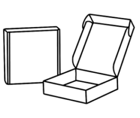 Bául
Bául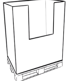 Box-pallet
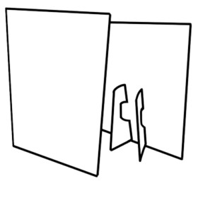 Displays
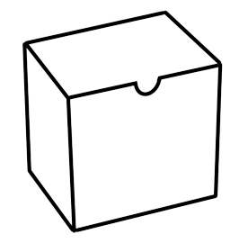 Estuchería
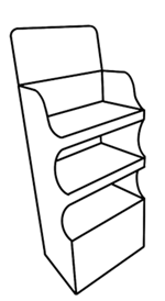 Expositor
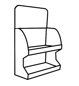 Exp.sobremesa
 Tótem
Tótem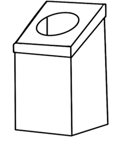 Otros
Otros
